Below is the standard Floppy Disk Controller of the IBM PC 5150. The “edge connector” on the left is intended to support the two internal floppy disk drive bays. On the back is a 37-pin external female connector, which can support two additional external disk drives.
The Wang system was involved in introducing the 5.25″ disk format in about 1980 (developed by Shugart). [ so I would expect one of the late 1970s Wang systems was first to use it ]
The TRS-80 Model II of 1979, which was actually a very expensive system (in contrast to the Model 1 and Model 3 versions), had an 8″ disk drive (mounted vertically next to its integrated screen, similar to the IBM Datamaster system that was released in 1981). As expensive machines, users would generally need the larger capacity offered by those larger disks.
Some microcomputer software was starting to become available on 5.25″ disks around 1980 (VisiCalc and Zork, as examples). The TRS-80 Model 3 of 1980 and the OSBORNE-1 of 1981 are two examples of systems with 5.25″ disk drive before the IBM PC 5150 release in late 1981.
To communicate with these disk drives through a processor, one needs some form of controller software (which can be built into a ROM chip). Such a controller has some memory to buffer up content to/from the disk, coordinate timing of actually read/writing data, and finding the disk index. It is up to the operating system to then establish standard conventions in how the data on the disk is to be organized (which requires additional software, implemented in the operating system).
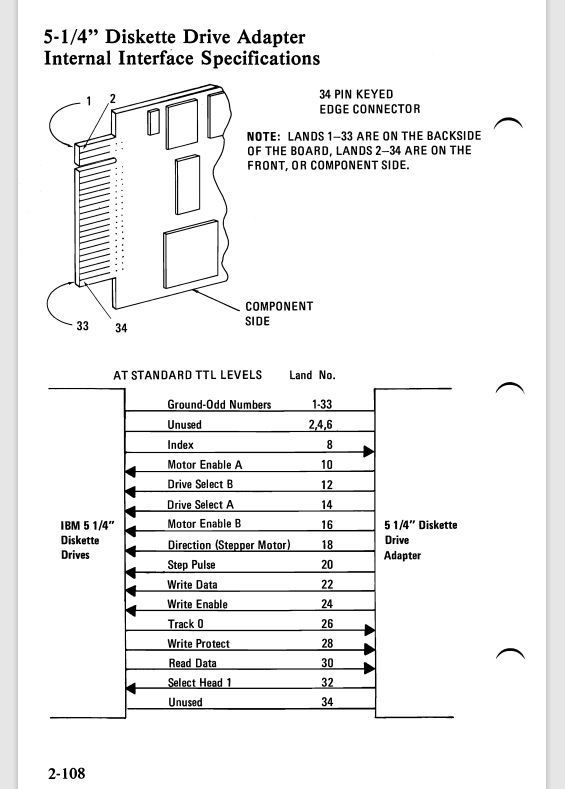
The connector is described in the IBM Technical Reference (2-108), where that manual also includes many other technical details about interfacing with the drives through the disk controller.


I’ve heard stories that the 37-pin external adapter can be used to read/write older 8″ disk drives, but I never saw this in person. 8″ disk drives were a bit before my time.
The 5.25″ disk drives use an “edge connector” (like old cartridge software, you slide the connector across the surface to make contact across the “top” and “bottom” of the edge).
The more modern 3.5″ disk drives, that were smaller and had more capacity, use a 34-pin connector. I didn’t want to use the physical 5.25″ disk drives in my 5150 (to save any wear and tear on the drives themselves, and also for the simple fact that I had no actual 5.25″ disks). The floppy disk emulators I ordered (described here) are 3.5″ devices, and so they use the 34-pin connector style. Despite this, these disk drive emulators can read and emulate 5.25″ disk images all the same (making it very convenient to switch between these formats without having to reboot or reconfigure the physical system).
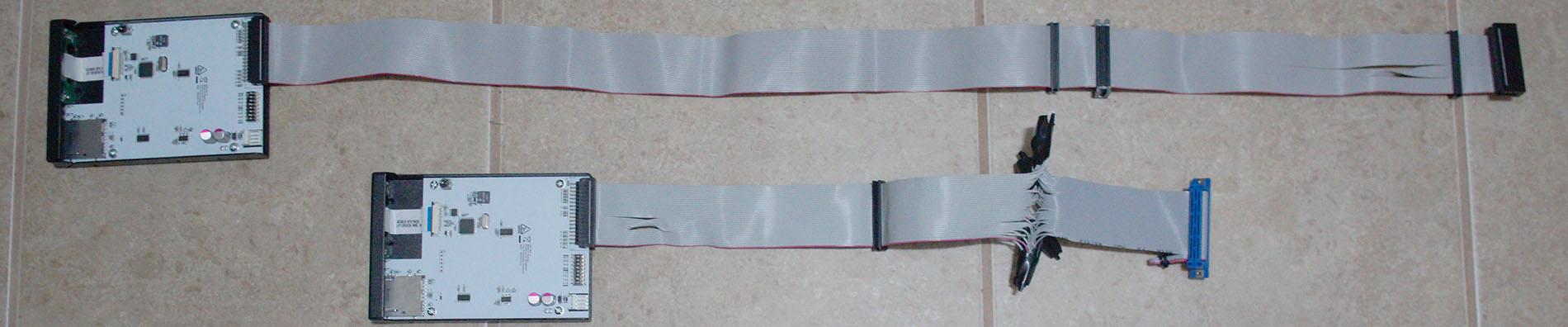
To make the 37-pin to 34-pin adapter for the external disk connector, I patiently made my own while watching a movie. Such a cable may exist somewhere, in a collection or in a long forgotten storage, but I wasn’t able to readily find one still for sale in any online source.
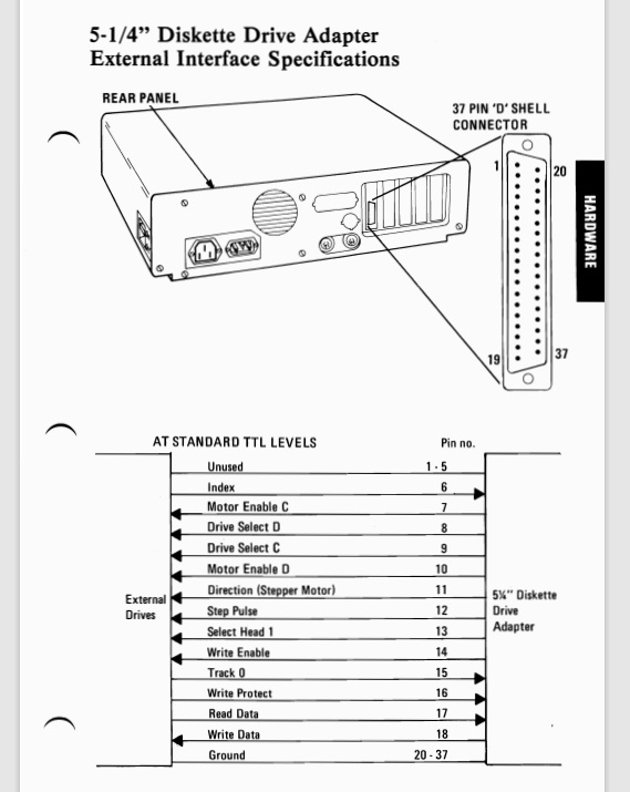
I did study the old IBM 5150 manuals that described these pin outs of the external connector, which I learned is called a “D”-shell connector (makes sense). After scratching my head for awhile and consulting the notes here (thank you Sir MinusZero), I proceeded on my way…

I found on Amazon one of these: “uxcell IDC Wire Flat Ribbon Cable DB37 Male to FC-40 Female Connector 2.54mm Pitch 20cm Length.” I have no cable crimp tool, so finding this helped a lot.
But this cable is a 37-pin to 40-pin connector, which is going in the wrong direction. However, if you look closely, it is actually a 37-pin ribbon that has been crimpled on — 3 wires on the end are simply not connected. Why they used a black 40-pin IDC, I just don’t know. If you can make it fit with your disk emulator, or even just “shave” the extra unused connector bits off — that might be one way to go. But for me, I couldn’t shove the 40-pin connector into my disk emulator in a way that I was comfortable with.
BELOW: Looking closely, you can see the last 3-wires of the connector aren’t used, so this is already a 37-pin ribbon.

So…
- Pry off the first three wires. Cut entirely or roll them up for some potential future use.
- Cut the 37-pin ribbon adapter (about in half or 3/4th way to the black connector). This removes the 40-pin IDC black connector.
- You can re-use this cut portion by “moving it over” (or “making a new red line), to reduce it down from 37-pin to 34-pin. [ except this doesn’t create a “twist” which means it may be limited to 1 external drive only ]
- OR…

What I did was found an old existing 34-pin floppy disk cable and spliced that on. Yes, all 34 wires one by one while watching a movie…. (correct, I have a stripper but not a crimper) And no, I didn’t bother soldering, don’t like smelling the smoke. This was just a proof of concept job. The only Quality Assurance I did was use an old Radio Shack voltage meter to do a continuity check on each pin.


And it worked! I set the motherboard dip switches to 4-drives, and DOS booted giving me A: B: C: and D:. A: and B: emulated by one HXC2001, and C: and D: emulated by another HXC2001 connected to the external 37-pin connector. If you add additional fixed drives, they will become E:, F:, etc. (depending on their number of partitions).
However, there can be a bit of confusion if you do 4-disk drives AND involve an XT-IDE at the same time. Many programs might insist that C: is your fixed-disk hard drive (even your PATH might be fixed to “PATH=C:\DOS;”). Also if you have an XT-IDE, you may need to press E or F in order to boot, since it will also otherwise try to always boot to C: (depends on version and settings).
Alternatively, you might prefer A: B: as the internal drives, then your fixed disk drive letters (C:) followed by the external drives (such as on E: and F:). There is a way to do this!
If you keep your disk drive dip-switches set to 2 drives, then A: and B: will get assigned as expected. Then C: becomes your fixed disk. Then, to access the remaining external disk drives, you need to add the following into CONFIG.SYS:
DEVICE=\DOS\DRIVER.SYS /d:2 /t:80 /s:9
DEVICE=\DOS\DRIVER.SYS /d:3 /t:80 /s:9
Some adjustment may be necessary. For example fully using C:\DOS, and /d:0 and /d:1 should be A: and B: already. Also some adjustment if you want larger capacity drive, if the DOS version and FDC can support it. But each “call” to DRIVER.SYS in this way will attach another drive letter in order of what is available.

BELOW: CheckIt V1.10 showing all 4x Floppy Drives.

This is neat because it offers a few possibilities:
- If you want to disable the internal drives but still have a way to bring content into the system by disk, you can just leave the two external disk drives connected
- If you have no XT-IDE or fixed disk, you can keep a BOOT disk in A:, game/app/program in B:, then use C: or D: as a scratch-pad (to make copies of the game or app).
- A good example is MOD files on C: and D:, read by a MOD-player on B:, with the BOOT disk remaining in A:. (another example is source code and compiling – have this on C: or D:, copy and test resulting compiled code to B:, etc.).
- Can help if you want to duplicate a disk in A: more quickly (script up a copy to B: C: and D: – the copies will still be done sequentially, you can go off and do other things while they are queued up)
- Again, if no XT-IDE (or fixed disk) is available, this a way to just have more disk images more immediately available – to switch between programs without having to fiddle with actually changing any disks.
Some limitations:
- You can’t boot from the external disk drives.
- No more than 2 drives will be running at the same time (kind of a power constraint with the original 63W power supply, but also a “lack of multi-tasking” constraint of this early DOS system)