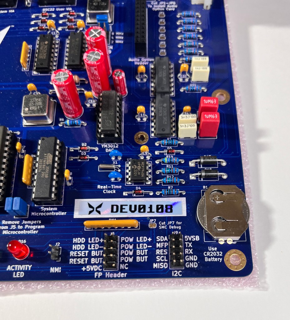
Here are some initial setup notes about the various connectors of the Commander X16 system. This is based on a “final” Developer Board received July 15th, 2023 (mine was DEV108).
FOR A SUMMARY LIST OF ALL MY Commander X16 related content, see here.
NOTES ON X16 USAGE (BASIC tokens, AUTOBOOT.X16, HEXEDIT, and more!):
The Commander X16 Launch SD Content Explained (and other X16 Usage Topics) — voidstar
UPDATE: See also setup notes at the X16 forum located at
Commander X16 Quick Intro FAQs for Setup – Commander X16 (cx16forum.com)
https://cx16forum.com/forum/viewtopic.php?t=7059
NOTE: I also have my “fan inspired” X16 intro-manual PDF available here… It is suited to be printed as a ~20 page manual in about a 7″ page format.
X16_MANUALS/CommanderX16_IntroducingYourX16_Manual_DRAFT_REV9.pdf at main · voidstar78/X16_MANUALS (github.com)
For a video about my X16 “first day setup” see YT title “voidstar’s Commander X16 Developer Board celebration kickoff 2023” HERE
Additional videos:
– X16 Promotion: https://www.youtube.com/watch?v=1n_4kE2SPt0
– X16 Audio Demo: https://www.youtube.com/watch?v=rgX4HjzRpq4
>>> You can click on most of the gallery images shown below to get a larger view <<<
TABLE OF CONTENTS
- Keyboard/Video/Mouse and Audio Connections
- Adapting to HDMI
- Power Connection
- SD2IEC: Additional/Alternate Storage
- Exploring User Port
- Additional Board Closeups (FP connections to case)
- BASIC SAMPLES
- “DOS” COMMANDS
- Monitor Commands (system assembler)
- GAMES and SAMPLES
- REFERENCES
- HISTORY
Keyboard/Video/Mouse and Audio connections
Uses standard PS/2 connectors for keyboard and mouse (mouse is typically “green” end connector, keyboard is typically “purple” end connector – those connectors also typically have a picture/diagram of a mouse and keyboard to remind which type and which way is “up” when inserting the connector). IMPORTANT: these PS/2 connectors are not hot-swappable (not PnP), so have the desired attachment inserted before powering on the system (or power it off before swapping or adding an attachment).
The X16 supports VGA, Composite, and S-Video out (only one is active at a time, not each at the same time). You cycle through the options by pressing SHIFT-SCROLL LOCK or using the “MENU” command from BASIC. The default is VGA. X16 also supports CTRL-ALT-DELETE for a system reset.
NOTE: The mouse PS/2 connector felt “snug” to me and the S-video port felt too loose. Be gentle, these shouldn’t be difficult to plug-in. Excessive force can bend or break the mainboard connectors.
NOTE ABOUT AUDIO: This is a “standard 3.5mm stereo” plug, can use headphones or amplified power speakers. Some monitors/CRTs will have an audio-in jack that can be used also. Unlike the Commodore PET or Apple ][, the X16 has no built-in/onboard speaker. You can find USB-C to “stereo audio plug” adapters if needed.


Adapting to HDMI
There are many brands of VGA and Composite video to HDMI adapters. The TENSUN model below was from Amazon and has worked well for me (has buttons to toggle between 480/720/1080 upconverting). All of these adapters will require their own power plug, because real-time video signal conversion just requires that much power, and should cost between $30 – $80.


Power Connector
The X16 has an “ATX” style connector on the side. This Developer Board came with a 12V adapter card that has a simple to use connector. Make sure the “clip” side of the ATX connectors are on the same side and the connector is all the way inserted (not just “half-way”! press all the way in).


The particular 12V adapter I am using came from some old electrical appliance a long time ago. It is rated at output 12V, 800mA (center positive polarity). These are “AC to DC 12V wall outlet” adapters and easily found on Amazon.

You can also use a regular “full sized” ATX power supply. I attached a 600W but I think the minimum is about 160W (because the included pico-PSU has a label on it saying 160W). Remember larger PSU fans should (in general) make less noise. There was a note about ensuring the PSU you use has a -12V rail.


A PSU with ATX 20+4 (24-pin) connector can be used. But older ATX PSUs (such as from the 1990s) may only have 20-pin, those can also work. The connector has a combination of square and “arched” plugs to help ensure that it can only fit one way (so if the plug being difficult, check the direction and don’t force it).


SD2IEC: Additional/Alternate Storage
I’ve verified that the SD2IEC disk drive emulator used on the C64 also works on the X16 (the one I have was from TFW8b). It is substantially slower than the onboard SD, but it verifies that classic C64 devices can be used.
The SD2IEC requires its own power. I recalled long ago that I got this 1530USB device for to use the Datasette on the PC (to assist with preparing recordings for the tape deck used by the Commodore PET). These are still available and work great for cleanly providing a power source to the SD2IEC.


The X16 internal SD card is set as Device 8. To deconflict with this, the SD2IEC needs to be moved over to Device 9. The commands I used are:
OPEN1,current address,15,"U0>"+CHR$(new address):CLOSE1
OPEN1,new address,15,"XW":CLOSE1   <-- this is to save the setting to EEPROM
After doing this, the X16 built in commands “DOS 9” and “DOS 8” could be used to swap between the two storage devices.

Exploring User Port
There are a variety of C64 User Port devices that we’ll explore eventually!
CAUTION: The X16 UserPort is more alike the VIC-20 UserPort than the C64 UserPort. So it turns out that as-is, C64 UserPort devices aren’t going to work on the X16. In particular, the X16 uses 6522 VIA chips. VIA#1 is used for some gamepad support. And while VIA#2 isn’t used by the system, the DEV board had the VIA 2 still connected to an active IRQ line. For the PR (production) board, a jumper has been added so that VIA #2 can be swapped to NMI (not-interrupted) – but no developers have had any time to really explore this, and so no UserPort peripherals are available for the X16 as of yet.


Additional Board Closeups
“FP” here means “Front Panel” (connectors for power, reset, LED lights typical on ATX cases). I have the official case on order and will report back how well this “FP” header works out. Meanwhile, the designers have thoughtful placed small POWER/RESET switches right on the motherboard.


BASIC SAMPLES
I came up with the following as a simple BASIC program that exercises a variety of features.
Example #1:
- changing screen resolution
- scanning for keyboard input key-presses
- invoke random number generation
- compound logic
- use of control-codes for changing color
5 SCREEN 6
10 W=20:H=15
20 GET A$
30 A=ASC(A$)
40 IF A = 27 GOTO 100:REM ESCAPE TO EXIT/QUIT
45 PRINT CHR$(INT(149+RND(TIME)*9));:REM SET SOME COLOR
50 X=INT(RND(TIME)*W)+1
60 Y=INT(RND(TIME)*H)+1
65 IF ((X=W) AND (Y=H)) THEN GOTO 95
70 LOCATE Y,X
80 PRINT CHR$(160+RND(TIME)*95);
90 GOTO 20
95 REM HANDLE LAST ROW/COL ISSUE
96 REM LOCATE Y,X-1:PRINT "A";:PRINT CHR$(157);:PRINT CHR$(148);
97 GOTO 20
100 SCREEN 1
110 COLOR 1,6:REM WHITE ON BLUE
120 END
Example #2: I wrote this example as a way to print out all the printable-characters within the ROM of the system. There are two main groups (32 to 127 decimal and 160 to 255 decimal), while the character output between those two groups are control characters of various sorts.
NOTE: use PRINT CHR$(14) to swap to lower case character set and PRINT CHR$(142) to swap back to upper case character set. These two choices give a different set of “extended” symbols to play with. This is same as the Commodore PET and Commodore C64 styles.
5 C=1
10 A=32:B=127
20 FOR I = A TO B
30 PRINT I,CHR$(I);
34 REM  CLOSE DOUBLE QUOTE, THEN LEFT ARROW ONE SPACE
35 IF I = 34 THEN PRINT CHR$(34);:PRINT CHR$(156);
40 C=C+1
49 REM ADJUST 7 TO A LOWER VALUE IF USING 40-COL
50 IF C>7 THEN GOTO 100
60 NEXT I
70 IF A > 100 THEN END
80 A=160:B=255
90 GOTO 20
100 C=1:PRINT:REM NEWLINE TO NEW ROW AND CONTINUE
110 GOTO 60

“DOS” COMMANDS
Here is a list of commands I’ve used and verified, so far…
UPDATE: These are the “long version” of the commands. In R46 (and the released System ROM), these commands still work, but there is also an even shorter abbreviated set of commands. But note that the following commands can also be used inside a BASIC program.
F7 works for listing directory (cannot use CATALOG or DIRECTORY). F7 = DOS”$
CLS                   clear the screen
DOS"$                 list current directory (F7)
DOS"S:<filename>"     SCRATCH(delete/erase) specified filename
DOS"R:<new>=<old>"    rename a file to new from old
DOS "CD:/"            back to root folder
DOS "CD:subfolder"    go to specified subfolder
DOS "CD:.."           move back up one folder
DOS 9                 set device 9 as default (do not use DOS "9")
DOS 8                 set device 8 as default (do not use DOS "8")
LOAD "filename"       load PRG or BAS
SAVE "filename"       save (generally to BAS)
SAVE "@:filename"     save and write to existing filename (overwrite)
BOOT                  runs autoboot.x16 within current folder
               (this is like LOAD "autoboot.x16" then RUN)
MENU                  activate internal settings menu
TIME$                 current time as string
DATE$                 current date as string (year is 2-digit!!)

Initializing a disk:
DOS"I                     initialize
DOS"$=P                   list partitions
DOS"CP1                   select partition 1
DOS"N1:SAMPLE,X16,FAT32"  new partition (X16 can be any ID)
Monitor Commands
The “built in monitor” is a system way to display and alter system memory address values. It is a bit hard to explain to those who have never used such a thing. It may be best learned by just using it with a few examples.
From BASIC, use the “MON” command to enter this built in monitor. Then try the following:
M 0400              monitor single 8 byte row starting at given address
M 0300 0380         monitor the given address range, slip into groups of 8 byte
D 0800              disassemble starting at 0800
        ( to write assembly instead of machine code, change the "," to "A" ! )
F3/F5               scroll UP/DOWN (during monitoring)
ENTER-ENTER         stop current command, return to monitor prompt (or try F7)
SHIFT-ENTER         newline, can enter new monitor commands
R                   show current register values
G                   go ("execute") at given address
X                   exit the monitor, return to BASIC
$ = hex, # = decimal
Use the arrow key to move around to byte values, then adjust them to new hex values (hexadecimal values only, 0-F), then ENTER to write/commit the value. If you move off without pressing ENTER, the value isn’t really written.
Example:
From startup BASIC type command “ROM” then do commands:
M 0800       <press ENTER>
4C 47 FF     <press ENTER to commit these to memory>
            (include the spaces after 4C and 47)
            (press ENTER again to go back to monitor prompt)
G 0800       <press ENTER twice>
The above is a very simple example that will just reset the system back to BASIC. “4C” is a jump instruction and FF47 is the target address, which is ROM code to enter back to BASIC. But this example demonstrates all the steps of using the monitor to enter code.
An alternative way to do this is to try the following:
D 0800       <press ENTER>
(move cursor over to replace "," with "A" for assembly)
(move cursor back to the assembler column)
JMP $FF47    <press ENTER twice>
The above should interpret the JMP $FF47 and put the “4C 47 FF” machine code automatically.


GAMES and SAMPLES
For the initial Developer Board, below is an overview of the suite of software content included on the SD card. These give a wide sampling of the audio and video capabilities of this system.
voidstar’s Commander X16 Developer Board celebration kickoff 2023 (warning: spoilers) – YouTube
The above is a link to a video to show these titles in action.


REFERENCES
- SHIFT-SCROLL LOCK: switch video modes
- CTRL-ALT-DEL: reset the system
- X16 Emulator, Technical Reference docs, System ROM code…
Commander X16 Community (github.com) - https://cx16.dk/cx16-petscii/
HISTORY
After several years of development, the first batch of X16 Developer Boards were made available for purchase on Thursday June 22nd, 2023 (the Thursday prior to the VCF Southwest 2023 weekend near Dallas, Texas). Only about 100 of these boards were made available for early-testing.
On October 31, 2023, pre-orders of the next batch of X16 were made available (up to about 1000 of them). These pre-orders began shipping in early January 2024.


Hi,
I just wanted to stop and say that this is a great “First things I could do with my X16” page and I like it. I didn’t find this page looking for that. I was looking for low level documentation of the X16. (Boot sequence (and how Expension cards rom code would be executed at boot)). When I saw your name in the result, I recognized it from the X16 Discord server (RS232, cartridge or peripheral channel). You came across like a knowledgable person, so I was hoping for some “insight” from the X16 section of your site.
anyway, this page is excellent and will be the one I refer people to when they ask about what is the X16.
Thanks for the note! The notes here were mostly intended as my initial impressions of the early DEV board. Fortunately, it’s turned out that much of all that still applies to the production PR board!! I’ve updated some of the notes here (specifically that on the X16 Forum, I do have a kind of “extended version” of these notes at the Forum, and also in a PDF document freely available to anyone interested).